Electronics
I've been experimenting with electronics since I was in elementary school, and I picked up a soldering iron for the first time when I was eleven years old. I spent a lot of time at Radio Shack, Mar-Vac Dow, and other electronics supply stores during those years. My email address ends in "ne555n" because that's the name of a timer IC I've used in projects.
Custom 20MHz Arduino board
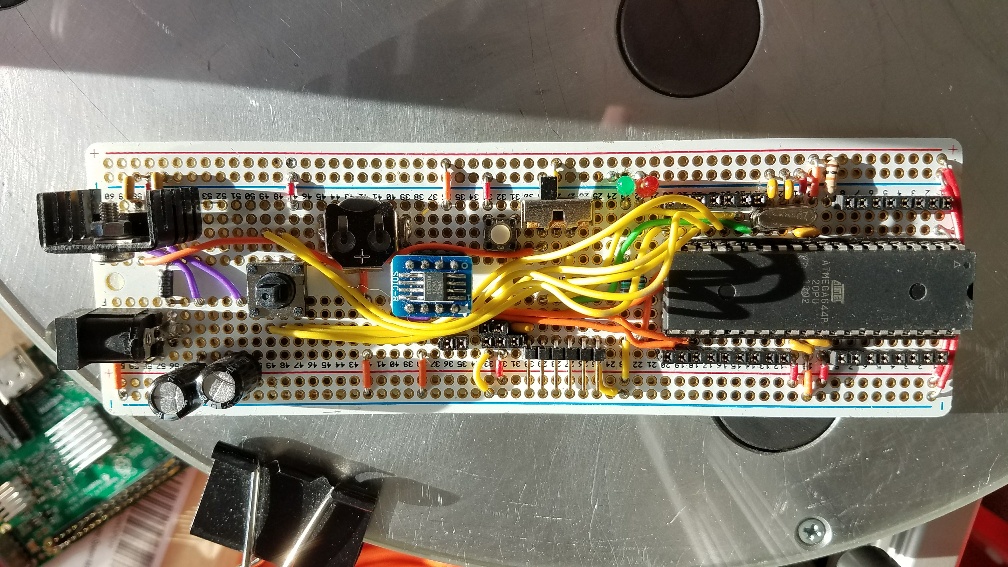 A custom Arduino board: Power supply on the left, DS3231 real-time clock in the middle, ATMega644 controller on the right.
One of my projects in recent years was a desktop clock. It kept track of the time very accurately, and it would also tell you the moon phase. It was programmed in the Arduino IDE, and used an ATMega644 microcontroller on a board I soldered up myself. Most Arduinos have 2K of RAM and 32K of flash, and run at 16MHz. The '644 has 4K of RAM, 64K of flash, and runs at 20MHz — and it can be reliably overclocked to 30MHz or more.
At one point, I had this board running NeoPixels. AdaFruit's Arduino drivers for these LEDs only support 8- and 16-MHz chips. I had to modify the driver to accommodate the '644, and it worked just fine. It turns out that the assembly language code, which has been carefully tuned so that the clock cycles taken by each instruction match up with the wire format of the protocol, run as well at 20MHz as they do at 16MHz. All I had to do was modify the #defines.
Using an oscilloscope to test a new device driver
Peripherals for Microcontrollers
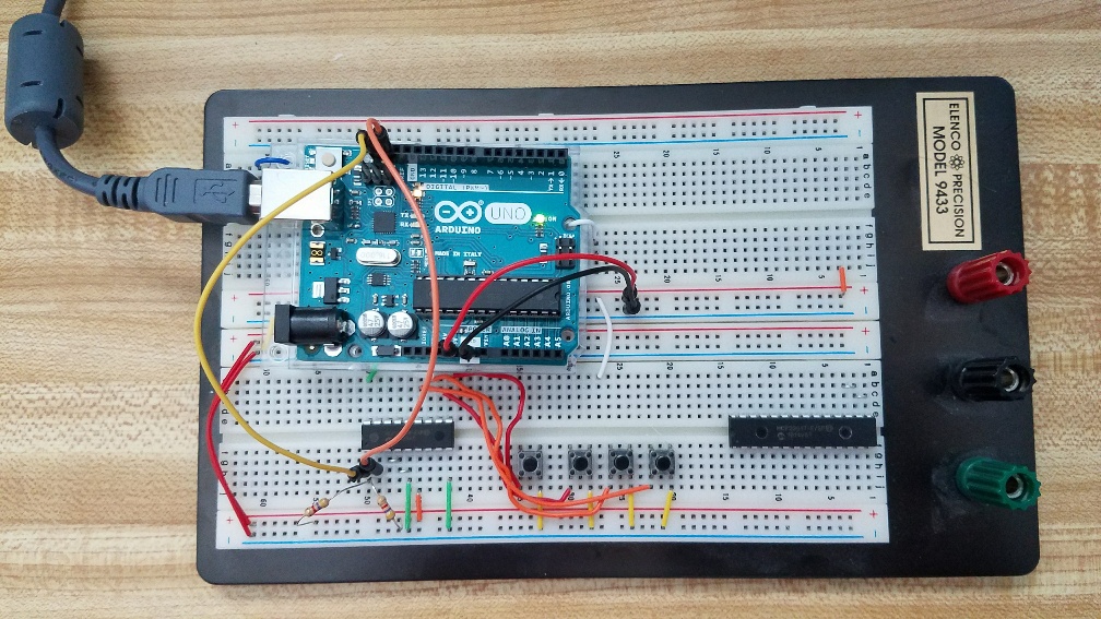 Prototype of a tac switch expansion board
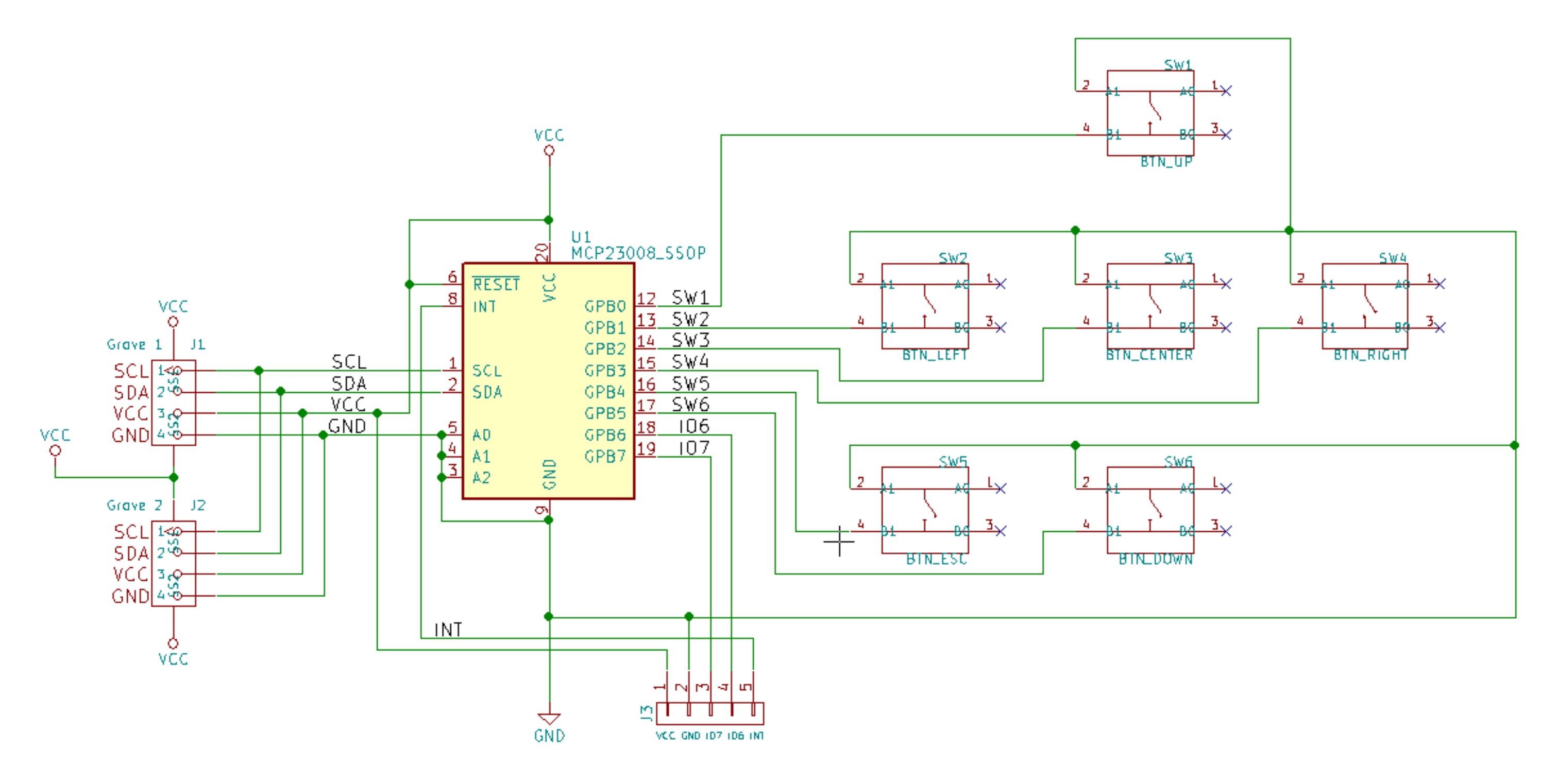 Circuit schematic in KiCad
 Part of the code that reads the button state
This is a prototype for an MCP23008-based "button board" that will work with Arduino, Raspberry Pi, Teensy, and any other microcontroller with an I2C interface. It will operate at anywhere from 1.8 to 5 volts, enabling it to work with a huge variety of microcontrollers.
The MCP23008 is an 8-bit "port expander." It's basically a fancy shift register that works over I2C. Up to eight lines can be either read or written. Six of them are dedicated to reading the buttons. The last two can be used to power small LEDs (under 25mA), or for whatever other purpose, and will be routed to solder pads in case the end user wants to do that. The port expander has internal pullup resistors. This means that the buttons can only work by being connected to ground. Because of this, the button pins will read high (1) when they aren't pressed, and low (0) when they are. This is the opposite of how I'd like it to work, so the code has a ternary operator that inverts the pin values if desired. The original design featured pullup resistors on the I2C lines, but I removed them as I think that's best implemented at the controller. The reference diagrams I've seen have multiple I2C devices on one bus, but only one pair of pullup resistors. The board has two connectors, so devices can be daisy-chained to it. The schematic and PCB layout are done in KiCad. I've also used Fritzing, and while aspects of it are more user-friendly, it doesn't seem to have as many features — or to enjoy as much acceptance — as KiCad. The board house I'm using has released its parts library and a bill-of-materials (BOM) exporter for KiCad, but not for Fritzing. Additionally, KiCad outputs 3D models of PCBs. That's useful for integrating finished boards into 3D-printed enclosures.Enclosure for IEC power connector, circuit breaker, and illuminated switch
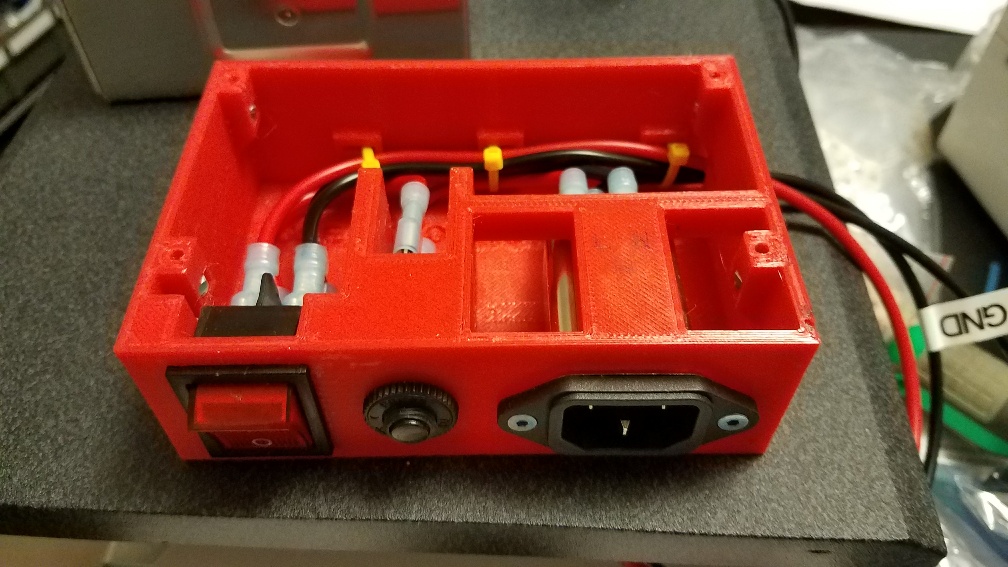 This enclosure keeps most of the high-voltage wiring contained.
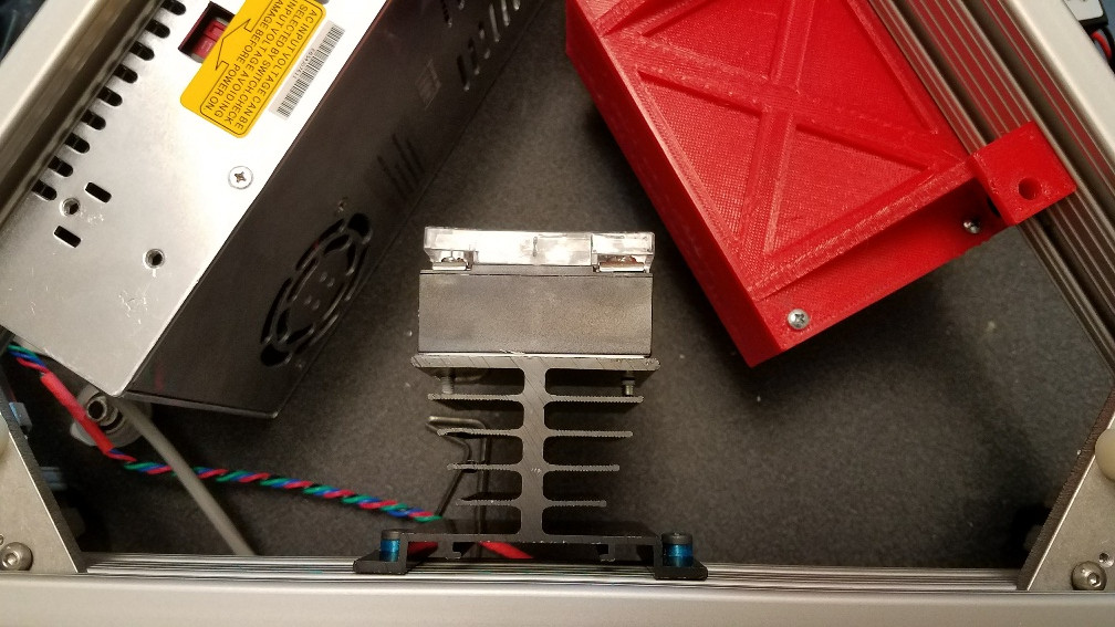 The enclosure after being installed, along with a Meanwell PSU and Auber DC solid-state relay.
This one was equal parts fun and scary. Before this project, I rarely did anything with high voltage because it wasn't necessary. However, I wanted to use Meanwell power supplies with my 3D printers, and they take line current through terminals rather than a socket. This was around the time I was getting ready to abandon SketchUp, but this enclosure was simple enough that I figured I could do it without running into any of SketchUp's problems. I decided to use an illuminated power switch, and to wire a circuit breaker inline for overcurrent protection.
The switch snaps directly into the front of the enclosure, where it holds itself in place. There is no provision for any fasteners, but the holding mechanism is pretty good, so none seem to be needed. The inside of the enclosure is designed to fit perfectly around the circuit breaker and IEC plug, keeping them aligned. The breaker is secured from the outside with a nut, and the IEC connector is held in place by two M3 screws and nylon locknuts on the inside. (I always use nylon locknuts on 3D printers because they won't come loose with vibration.) In the back of the enclosure, the wires are held fast by zip ties that feed into channels that have been printed directly into the box. That would be quite difficult to achieve with injection molding. I am concerned that over time, the zip ties might begin to cut into the wires due to vibration. I think the next step is to immobilize them with some combination of heat shrink tubing and hot glue. The lid/mounting bracket is secured to captive nylon locknuts near the top of the enclosure.
The tricky part was the illuminated switch. It's pretty easy to get it working without illumination — one wire goes in, another wire goes out, and you can figure out which goes where by using the continuity test function on a DMM. Getting it to light up when it's turned on is another matter. It came without a wiring diagram. The advice I got from Google was ambiguous, and I wasn't quite sure, but I wanted to give it a shot. I wired it up the way I thought it should be, which was wrong. I switched it on, and that let the smoke out with a series of loud pops. Nearly triggered the fire alarm!
After getting some advice directly from an electrical engineer, I installed a new switch and wired it up correctly. I was still nervous about turning it on, but persevered. I took it outside, made sure the switch was off, set it down ten feet from the socket, made sure my fire extinguisher was charged, and plugged it in. No smoke! I unplugged it, turned the switch on, and plugged it in again. Still no smoke — and the switch lit up!
Solid-State Relay for Heated Bed Control
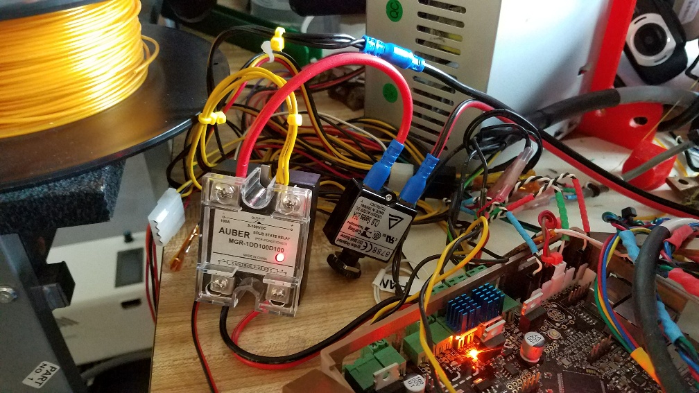 Auber DC SSR
3D printers use field-effect transistors (FETs) to control heaters. This is because their microcontrollers can only gate a few milliamps of current, which is exponentially less than necessary. A small through-hole FET is quite adequate to control a hot end's heating element, which is only 30-40 watts. However, the same FETs are also used to power the heated bed, which consumes hundreds of watts. It can be done, but is far from ideal. The internal resistance of a regular small FET is simply too high. A great deal of current gets turned into waste heat, and that heat tends to do bad things — like slowly melting power connectors over many months.
The easiest way to solve this problem is to use a solid-state relay, or SSR. It's basically a huge FET with very low internal resistance. Whereas the 3D printer controller's built-in FET gets scaldingly hot to the touch, a proper DC SSR can pass twenty or thirty amps at twelve volts and barely exceed room temperature. Some people like to use really expensive SSRs that cost around $100, but I've found that Auber's DC SSRs are very good at what they do, and they only cost about $20.
Following advice on some forums, I originally had the SSR wired to gate the ground side of the circuit. A +12V line from the PSU was wired directly to the heated bed's positive terminal, and then the negative terminal went through the SSR. This seemed odd to me, and not as safe as it should be. I eventually switched it so that the SSR was gating the +12V line instead. That way, no potential energy would be hanging out in the heated bed unless the SSR was on. I reasoned that that would be much safer. It definitely made it easier to PID-tune the heater.
On the subject of PID tuning, it's easier to do that when you're using the controller's on-board FET. This is because it turns a lot of current into waste heat, limiting the total power delivered. When you switch to a very low-resistance SSR, the system can deliver significantly more current to the heater, and that means it will heat faster than it could otherwise. This can very easily lead to wide temperature swings, in which the temperature keeps oscillating up and down by a large amount. The cure for this is to use a very large value for D. P and I might be something like 150 and 5, but I found the only way to get a stable temperature was to use somewhere around 2250 for D. After I figured that out, I got the system to hold temperature to within 0.5° C or better.
The SSR connects to the heated bed via a circuit breaker. In the future, I'd like to add two thermal fuses, epoxied to the bottom of the heated bed and connected in series. If the SSR fails open, it will deliver +12V to the heated bed regardless of whether the controller is telling it to or not. That could cause a thermal runaway condition, and perhaps even a fire. With two thermal fuses in series, three components would have to fail open (instead of just one) for that to happen.
Wiring Harnesses
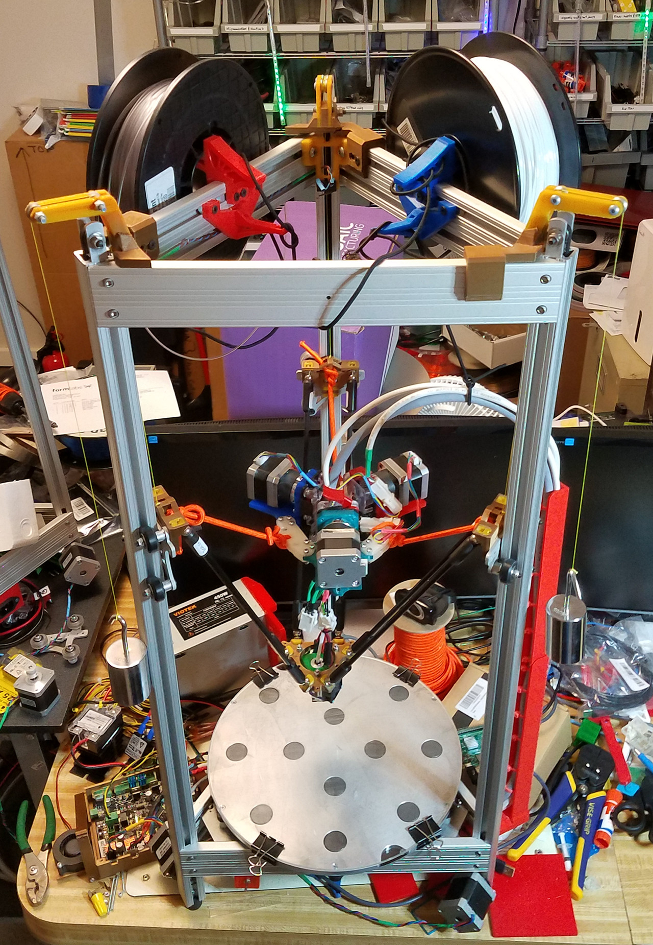 Rostock MAX Metal, showing counterweighted flying extruder system and cable mast
If you build a 3D printer from a kit, you'll probably wind up fabricating a wiring harness sooner or later. I've mostly used regular multi-conductor cable — sometimes speaker wire — for this purpose, but have recently switched to using specialty robotics cable from McMaster-Carr. This cable is designed specifically to withstand motion, twisting, and vibration, and is thus less likely to develop problems. It's also shielded, so there's less worry of EM interference.
I use connectors from TE Connectivity. They're sold at Mouser, and other electronics supply sites. I use a ratcheting wire stripper to strip the ends. Then, I use pliers to crimp the pin/socket pieces. I usually flood the crimps with solder after they're tightened, but I'm not sure if that's particularly useful. It does seem like it would make the connections less likely to fail. After that, I insert the crimps into their housings, use a DMM in continuity test mode to make sure the wires are going to the right places, and then plug them in to run a "smoke test."
The wires in proper robotics cable have numbers printed on them, so it's fairly easy to figure out what's what at either end. I keep notes on which wires are supposed to do what, so they're all standardized and interchangeable.
The robotics cable originates at the 3D printer controller, which is always located underneath the machine. The cable runs up through a cable mast, arcs over to the center of the machine, and descends to the hot end. The top of the arc is usually Bungeed to a strain relief mast at the top of the printer. The Bungee cord helps support its weight, and also constrains it from getting stuck between the carriages and endstop switches during homing. The cable provides connections for many things:
- PWM for hot end power
- Hot end thermistor
- Z-probe signal
- +12V PWM for part cooling fans
- +12V for always-on fan that cools the hot end's heat sink, which is shared with the LED ring
- +5V for Hall-Theta Z-probe
- Ground connections for everything
That's 12 conductors in all. Each stepper also requires a four-conductor cable. I've been using simple speaker wire for this purpose, but have recently switched over to 4-conductor robotics cable.
These cables seem to last for 1-2 years before developing issues. I think the next step is to develop better strain relief for the wires, especially around the connectors. That's always where they get unreliable. The cables in the photo descend through the center of the flying extruder platform, and that keeps them from moving around too much relative to the hot end, but I think something that keeps the wires immobilized relative to the connectors would be better.