3D Printing
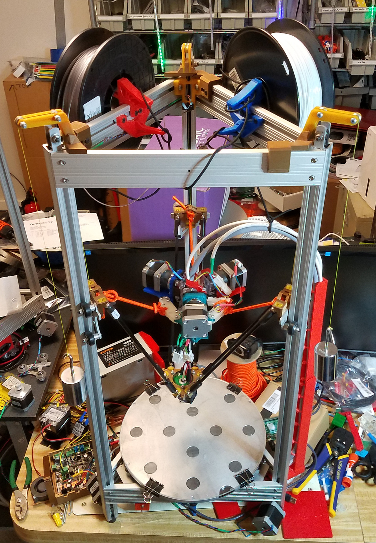 The complete printer, including the cantilevered counterweight pulley masts. Fishing line runs over V-groove pulleys.
I've been working with 3D printers since 2013, and have made significant open-source contributions that are used by hundreds of people. I get a real kick out of knowing that I can help people solve problems that they used to think were impossible.
All told, I've released 21 open-source products for 3D printers. Some examples:
- Heuristic calibration system for improved dimensional accuracy (firmware)
- Flying triple extruder mount, including counterweight system (see 2nd video)
- Arm mounts for extruders (see 1st video)
- Blower ducts for part cooling (see 1st video)
- Two Z-probe mounts (used for calibration)
- Several hot end mounts (see 1st video)
- Filament spool holders (being printed in 1st video)
- Enclosures for controller boards & touch-screens
- Cable mast (see 2nd video)
- LED ring snap mount (see 1st video)
- Cable clip with flexible retainer
I've also produced some non-open-source products:
- Carriages & effector for magnetic arms (see 2nd video)
- Many depth gauges, for use while pouring candles in a factory
- Fixturing for my Probotix CNC router (see below)
- A 3D-printed lamp
- A personal beauty product (under NDA)
I have significant experience building, upgrading, and operating "linear delta"-style 3D printers, like the one in the video. I also have experience operating FormLabs' Form 2 3D printer, which uses a very different process called stereolithography. I know a lot about how to design objects for both types of printer, and can take into account factors such as support structures and overhangs.
CNC Milling
A CNC router is a device which moves a cutting tool in two or more axes (usually 3, but sometimes 4 or 5). I used mine to drill 197 boards to go on a coneyor belt at a candle factory. I also helped the owner select the right kind of plywood, and did some calculations to make sure that the drive motors had enough torque to handle the weight of the boards and everything that would go on them. (My client didn't ask me to do that. I just thought it was a good idea.) These boards, and the depth gauges mentioned above, have been used to produce over one million candles.
In the video, you can see the router doing a dry run of the program I used to mill the boards. This was done by modeling the boards in SketchUp, placing all of the drilling points, and exporting to EMC2, which runs on the computer that controls the machine. I had it set up to drill three of them at a time. The fronts were drilled first. The boards were then flipped over, and pockets were milled in the backs. The production run took about 20 hours.
The router uses a standard 1/4" end mill. Some of the holes, and all of the pockets, are wider than that. The CNC machine compensates for this by doing a "plungebore" operation: the router is moved downwards in a spiral, rather than a straight line. You can see it doing this in the video, accompanied by a sort of wobbling sound.
The router doesn't have a way to sense the position or orientation of the boards, so it's vital that they all be lined up perfectly. The corner of the first board has to rest at the router's home position (X=0, Y=0), and the boards have to be perfectly square with the edges of the router. Otherwise, the holes and pockets will be milled in the wrong places. To this end, I designed several fixturing pieces, which you can see in the video. They were 3D printed in white plastic. Some of them are there to ensure proper placement and angle, and some of them serve as hold-downs. Designing, printing, and revising these pieces added about 15 hours to the job. In return, I was able to deliver a product that conformed perfectly to the specifications. The boards were installed without a hitch, and are still in use to this day.